

top of page

What Is a Drum Chipper and How Does It Work?

A Drum Chipper turns logs, branches, and mill residues into chips through a controlled mechanical process. Material enters through an infeed system, where rollers guide it toward a rotating drum fitted with sharp knives. Each knife slices wood against a fixed surface. The resulting chips pass through a screen or discharge opening, while oversized pieces may remain for further cutting. The sound is unmistakable: steady engine noise, wood feeding in, and chips rattling into a collection bin.

For transparency, the expert and quotation below are illustrative, not a verified real-world attribution. Fictional wood-processing engineer Daniel Mercer puts the core idea this way: “A good chip starts with a steady feed and knives matched to the material.” It is a simple line, but it points to real operating variables. Wood species, moisture, feed speed, knife condition, and screen size can all affect chip quality and machine performance.

This guide explains the main components, the cutting sequence, and the factors operators monitor. It also looks at common applications and practical maintenance checks. A chipper is not magic. Dull knives, uneven feeding, or unsuitable material can produce inconsistent chips and unnecessary strain. The details matter. Some setups also demand trade-offs between output size and throughput, and there is no single setting that suits every job.
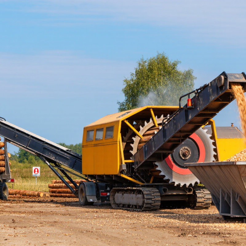
What Is a Drum Chipper and How Does It Work?

What a Drum Chipper Is: Its Main Parts and Role in Wood Processing

A drum chipper is a wood-processing machine that cuts branches, slabs, and small logs into chips. Its central component is a rotating steel drum fitted with sharp knives. As wood enters, the knives slice it against a fixed anvil. The action is fast, but chip quality depends on more than drum speed.

The feed chute guides material toward the cutting area. Feed rollers grip and advance the wood, helping maintain a steady flow. The drum and knives do the cutting; the anvil provides a firm counter-edge. A motor and drive system turn the drum, while the housing contains the cutting zone. Chips leave through a discharge chute and can be directed into a bin or vehicle.

Simple parts. A precise interaction.

In practical use, knife sharpness, anvil clearance, and wood condition all affect the result. Dull knives can produce ragged chips and place extra strain on the machine. Wet, crooked branches may feed unevenly, even when the equipment is adjusted correctly. That detail is easy to underestimate. Operators should follow the machine’s instructions, keep guards in place, and avoid reaching into the feed opening. Chip size is not perfectly uniform; wood grain and branch shape make a difference.

How Feed Rollers and Rotor Knives Convert Wood into Chips

A drum chipper uses feed rollers to draw branches and logs toward a rotating drum. The rollers hold the wood and control how quickly it enters the cutting chamber. Their pressure matters: too little can let a crooked branch bounce, while steady pressure helps maintain a consistent feed. You can hear the rollers change pitch as thicker wood passes through. Small pauses happen.

Inside the housing, knives mounted on the drum sweep past a fixed bed knife. Each pass slices off wood, rather than grinding it into pulp. The chips then leave through the discharge chute. Knife sharpness, drum speed, and feed rate all affect chip size. A clean, sharp edge usually cuts more evenly; a worn one can tear fibers and leave rough fragments.

In practice, the output is rarely perfectly uniform. Wet wood may cling together, and knots can make a branch feed unevenly. Operators adjust the feed to match the material, but that judgment takes experience. It is easy to assume faster feeding means higher output; sometimes it only produces irregular chips or strains the machine. Keep guards in place and use the controls from the designated operating position.

How Drum Speed and Knife Settings Affect Chip Length

A drum chipper cuts wood as rotating knives pass a fixed anvil. At a constant feed rate, raising drum speed usually shortens the theoretical chip length because the knives make more cuts per minute. More knives have a similar effect. For example, at 1,000 rpm, two knives, and a feed rate of 20 metres per minute, the theoretical cut spacing is about 10 mm. Real chips vary.

Knife settings matter, too. The knife’s position relative to the anvil affects the bite, cutting force, and chip consistency. A wide clearance can encourage torn edges and uneven pieces; a tight setting may increase wear if the machine is poorly adjusted. Dull knives can also produce ragged chips, even when speed and feed settings look correct. Wood species, knots, moisture, and feed slippage add variation. Small changes matter.

The target depends on the end use, not just the machine. ISO 17225-4:2021 classifies graded wood chips, including P16S, whose main particle-size range is 3.15–16 mm; the standard also addresses fines and oversize pieces. This is a useful reference, not a guarantee that every chip will match the nominal range. Operators should check samples with sieves and adjust feed rate or knife setup gradually. I’d treat calculated chip length as a starting point, then verify the actual output.

What Is a Drum Chipper and How Does It Work? — How Drum Speed and Knife Settings Affect Chip Length

Operating Factor Example Setting or Condition Effect on the Chipping Process Practical Guidance
Drum chipper action A rotating drum carries knives past a stationary anvil as wood is fed into the machine. Each knife cuts a chip from the advancing wood; the resulting chips are discharged from the cutting chamber. Keep the feed system, anvil, and cutting components aligned and maintained according to the machine manual.
Drum speed Higher drum revolutions per minute, with feed speed and knife count held constant. More knife passes occur per minute, generally reducing the theoretical distance between successive cuts and producing shorter chips. Use the manufacturer’s permitted speed range. Drum speed alone does not determine final chip dimensions.
Feed speed Faster wood feed, with drum speed and knife count held constant. More wood advances between successive knife passes, generally increasing theoretical chip length. Adjust feed gradually and check chip consistency, feed stability, and motor load.
Number of effective knives More knives making effective cuts per drum revolution, at the same drum and feed speeds. Increases the number of cuts per minute and generally decreases the theoretical cut spacing. Use the correct knife arrangement for the drum. All installed knives should be properly matched and set.
Worked example: baseline 600 rpm; 4 effective knives; feed speed 24 m/min. Estimated cut spacing: 24,000 mm/min ÷ (600 × 4 cuts/min) = 10 mm. This is an idealized calculation, not a guaranteed finished-chip length.
Worked example: faster feed 600 rpm; 4 effective knives; feed speed 30 m/min. Estimated cut spacing: 30,000 mm/min ÷ (600 × 4 cuts/min) = 12.5 mm. Compared with the baseline, faster feed increases the theoretical spacing between cuts.
Worked example: faster drum 750 rpm; 4 effective knives; feed speed 24 m/min. Estimated cut spacing: 24,000 mm/min ÷ (750 × 4 cuts/min) = 8 mm. Compared with the baseline, faster drum rotation decreases the theoretical spacing between cuts.
Knife sharpness and condition Sharp, undamaged knives versus dull or nicked knives. Dull or damaged edges can cause rough cuts, fines, irregular chips, and increased power demand. Inspect and sharpen or replace knives using the specified procedures; follow safe lockout practices.
Knife projection and setting Projection and clearance set to the machine manufacturer’s specification. Incorrect settings can affect cutting quality, chip consistency, wear, and the risk of knife-to-anvil contact. Do not apply a universal projection value. Measure and set knives using the instructions for the specific machine.
Wood and feedstock condition Species, moisture, knots, branch structure, and piece size vary. These factors influence how wood fractures and feeds, so actual chip dimensions can differ even at unchanged settings. Assess chip samples under representative operating conditions before making further adjustments.

Note: The worked examples estimate ideal cut spacing using feed speed ÷ (drum revolutions per minute × effective knives). Real chip length and shape also depend on machine geometry, knife condition and setting, feed behavior, wood characteristics, and other design features. Example speeds and feed rates are illustrative—not universal operating recommendations.

How ISO 17225-4 Classifies Chips: P16S, P31S, and P45S

A drum chipper feeds logs or branches against rotating knives, producing wood chips that pass through a discharge screen. Knife condition, feed rate, and wood shape all affect the result. The machine setting helps, but it does not determine the final ISO size class by itself.

ISO 17225-4 classifies wood chips by measured particle-size distribution. P16S, P31S, and P45S indicate progressively larger nominal top sizes: about 16, 31.5, and 45 millimetres. The “S” classes allow defined ranges of smaller and larger pieces, so each batch is assessed by sieving rather than by its largest visible chip. Not every piece matches the number.

P16S chips are generally finer and can suit equipment designed for smaller fuel particles. P31S is a mid-range option, while P45S contains coarser pieces that may need a compatible feed system. A chipper operator can change screens or adjust feed settings, then check a sample against the standard. Real batches are rarely perfectly uniform. That variation is worth considering when selecting fuel, because bridging or uneven feeding can occur if the chip size does not suit the appliance.

What Is a Drum Chipper and How Does It Work?

A drum chipper feeds wood against rotating knives mounted on a drum, cutting it into chips. The resulting particle-size distribution depends on factors such as the feedstock, knife condition, and machine settings.

ISO 17225-4 Chip Classes: Nominal Top-Size Designations

This chart compares the nominal top-size sieve designations: P16S, P31S, and P45S. These labels do not mean every chip has the same size; classification is based on particle-size distribution and the applicable standard limits.

How Capacity, Power Demand, and Safety Guide Chipper Selection

A drum chipper uses knives mounted on a rotating drum to cut branches and woody material into chips. Feed rollers draw material toward the drum, where the knives slice it against an anvil. The result depends on knife condition, feed rate, and the material’s size and moisture. Dull knives can increase strain and produce uneven chips. Small details matter.

Capacity figures need context. A stated maximum branch diameter is not a promise of steady output, especially with wet, forked, or dense wood. Check the expected hourly volume and the typical material, not only the largest piece you might process. Ratings can mislead. I would leave a margin: clean test material rarely matches a real pile of tangled branches. That margin may mean choosing a larger machine, but it can prevent frequent jams and slowdowns.

Power demand rises when the chipper handles heavy loads or feeds material quickly. Match the drive system and available power to the workload, and consider transport and fuel needs too. Safety deserves equal weight. Look for guarded moving parts, accessible emergency stops, and a feed system that keeps hands away from the drum. Operators should follow the manual, wear suitable eye and hearing protection, and never push material by hand. Even a familiar machine can surprise you.

bottom of page