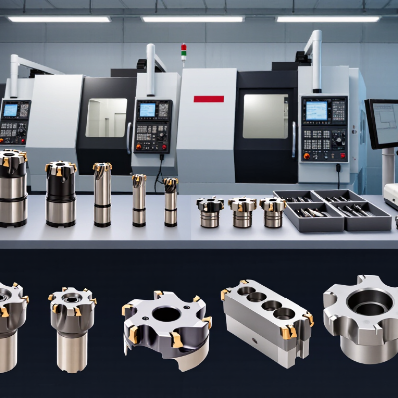
| Radial and axial runout | Require ≤ 0.02 mm | Measure the assembled cutter on a calibrated tool presetting machine or precision dial indicator. Check at the cutting diameter and record radial and axial readings separately. | Lower runout improves edge consistency, reduces uneven tooth loading and helps maintain the specified chamfer width. |
| Runout measurement condition | Measure with the actual holder, collet or arbor used in production; clean all mating surfaces before testing. | Request a documented inspection report showing the tool, holder type, measuring location, temperature and instrument resolution. | Runout from the cutter alone may not represent the runout of the complete tool assembly. |
| Carbide grade classification | ISO 513 K10–K20 cemented carbide for cast-iron applications | Confirm the carbide grade category and obtain a material certificate or grade specification from the manufacturer. | ISO 513 K grades are intended primarily for cast irons. K10 generally favors wear resistance, while K20 provides a higher toughness balance. |
| Workpiece material | Gray cast iron, ductile iron and compacted graphite iron can be evaluated with K-category carbide; select the final grade according to hardness, inclusions and interrupted cutting. | Provide the manufacturer with the workpiece grade, hardness, casting condition and machining stability. | Correct grade selection depends on the workpiece and cutting conditions, not only on the cutter geometry. |
| Cutter body material | Precision-ground alloy steel or hardened tool steel body with stable clamping features. | Check body material, heat-treatment information, concentricity records and visual quality of the shank and mounting surfaces. | A rigid and dimensionally stable body helps preserve runout and chamfer accuracy during repeated machining. |
| Cutting-edge geometry | Specify chamfer angle, chamfer width, number of flutes, cutting diameter and tool included angle according to the component drawing. | Compare the dimensional inspection report with the approved drawing. Confirm whether the tool is designed for axial, radial or interpolation cutting. | Incorrect geometry can cause oversize chamfers, uneven edge blending, vibration or insufficient clearance. |
| Dimensional tolerance | Define tolerances for cutting diameter, shank diameter, chamfer width and included angle before production approval. | Require a first-article inspection report using calibrated micrometers, optical measurement equipment or a coordinate measuring machine where appropriate. | Clear tolerances prevent disputes and ensure that the cutter matches the component’s functional edge requirements. |
| Surface finish of ground surfaces | Grinding should be uniform and free from visible burns, cracks, burrs and deep grinding marks. | Use visual inspection and, where required, a surface roughness tester on the shank, locating face and relevant cutting surfaces. | Good surface quality supports reliable clamping, reduces friction and lowers the risk of premature edge damage. |
| Balance and operating speed | For high-speed operation, request a stated balancing grade and maximum recommended rotational speed based on the complete assembly. | Verify the balance report and ensure that the holder, cutter and machine speed remain within the supplier’s stated limits. | Imbalance increases vibration, noise, tool wear and the risk of poor chamfer surface quality. |
| Coating suitability | Choose coating only after considering cast-iron abrasiveness, cutting temperature, coolant use and required tool life. | Ask for coating type, coating thickness range, deposition date or batch traceability, and recommended cutting conditions. | Coating performance depends on substrate, edge preparation and application; it should not replace correct carbide-grade selection. |
| Quality-control documentation | Require traceable inspection records for runout, dimensions, carbide grade and final visual inspection. | Check that each report includes a tool or batch number, inspection date, equipment identification and acceptance result. | Traceability makes supplier comparison objective and simplifies root-cause analysis if machining results change. |
| Production validation | Approve the cutter through a controlled sample test using fixed spindle speed, feed rate, cutting depth, coolant condition and workpiece material. | Record chamfer width, edge quality, cycle time, tool life, vibration and the number of rejected parts. | A practical cutting test confirms whether laboratory precision translates into stable production performance. |