

How to Choose the Right Solenoid Valve?
Choosing the right Solenoid Valve is less about selecting the cheapest component and more about matching it to real operating conditions. A valve may look suitable on a catalog page, yet fail when exposed to dirty air, hot water, aggressive chemicals, or repeated pressure changes. The correct decision depends on fluid type, operating pressure, temperature, flow rate, port size, voltage, response time, and installation environment.
As valve engineer R. W. Sloley has stated, “The valve is the final control element.” That short sentence deserves attention. A Solenoid Valve directly affects whether a machine starts, stops, fills, vents, or protects itself. Choosing normally closed or normally open operation can change the system’s safety response during power loss. Coil voltage must match the control circuit. Seal materials must suit the medium. Even a small mismatch can cause leakage, overheating, or unexpected downtime.
Practical inspection also matters. Check the arrow on the valve body. Confirm the pressure range at the actual temperature. Examine the pipe connection, enclosure rating, and available maintenance space. A compact valve may fit neatly, but its orifice could restrict flow. A higher-flow model may consume more power than the panel can provide. There is no perfect choice. There is only a choice that fits the application honestly, including its weak points. This guide explains how to compare Solenoid Valve designs, specifications, materials, and failure risks before installation.
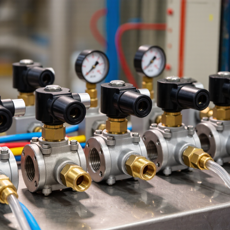
Define the Medium, Pressure, Temperature, and Required Flow Rate
How to Choose the Right Solenoid Valve?
Define the Medium, Pressure, Temperature, and Required Flow Rate
Start by identifying the medium moving through the valve. Water, air, oil, steam, and corrosive chemicals require different sealing materials. Check the fluid’s viscosity, cleanliness, and chemical compatibility. Small particles can damage a valve designed for clean media.
I have learned that “water service” is not always simple. Hot, treated, or contaminated water can change the selection completely.
Pressure needs careful attention. Record both the minimum and maximum working pressure, not only the normal value. Confirm the pressure difference across the valve, because some designs need a minimum differential pressure to open reliably.
Temperature also matters. Measure the actual medium temperature, plus nearby ambient heat. A valve rated for room temperature may fail beside a hot pipe.
Flow rate should be calculated from the system’s real demand. Use the required flow, connection size, and pressure loss together. An oversized valve may respond poorly at low flow. An undersized valve can restrict the system and create unwanted noise.
Check the flow coefficient provided by the manufacturer. Then compare it with measured operating conditions. It is easy to trust a catalog table too quickly.
A final review should include cycling frequency, installation direction, voltage, and available maintenance space. Keep it practical.
Select Valve Action: Direct-Acting or Pilot-Operated at 0.3–1 bar ΔP
How to Choose the Right Solenoid Valve?
At 0.3–1 bar differential pressure, valve action becomes a practical decision, not a catalogue detail. Direct-acting valves move the plunger with the coil’s magnetic force. They can usually open without upstream pressure, making them useful for low-pressure lines, dosing equipment, and small flow rates. Their limitation is size. Larger ports require more magnetic force, which can increase power consumption and heat. Pilot-operated valves use line pressure to lift the main diaphragm. They handle higher flow through compact bodies, but they normally need a minimum differential pressure, often around 0.3 bar. Below that point, opening may be slow or impossible. Check the exact specification.
Tips: Measure pressure at the valve inlet and outlet during operation. Static readings can mislead you. Confirm the minimum ΔP under the worst flow condition. Also inspect fluid viscosity, temperature, and contamination.
A useful selection check is simple: if the line may approach zero differential pressure, consider direct action. If stable pressure remains between 0.3 and 1 bar, pilot operation may provide better flow efficiency. However, this is not automatic. I have seen pilot valves fail during startup because the pump created pressure too slowly. The designer had checked the normal pressure, but not the starting condition. That small oversight changed the result.
Review coil duty, response time, port size, and installation direction before approval. A technically suitable valve can still perform poorly when the real pressure profile is ignored.
Size the Orifice and Calculate Flow Using the Manufacturer’s Cv Data
Choosing a solenoid valve starts with the orifice, not the pipe connection. The orifice controls how much fluid can pass through the valve. A larger opening may increase flow, but it can also raise power demand and create slower shutoff. Measure the required flow, inlet pressure, outlet pressure, fluid temperature, and medium type before selecting a size. Small details matter.
For water-like liquids, a common starting formula is Q = Cv × √(ΔP / SG). Here, Q is flow in gallons per minute, Cv is the manufacturer’s flow coefficient, ΔP is pressure drop in psi, and SG is specific gravity. I have found this estimate useful during equipment checks. It is not a final answer. For gases, use the manufacturer’s gas-flow equation because pressure ratio, temperature, and choking can change the result. Check the published Cv at the valve’s actual opening condition. Some data reflects full opening only.
Do not match the valve size to the pipe automatically. A 25-millimeter pipe may need a smaller orifice if the required flow is modest. Review the valve’s minimum operating pressure, maximum pressure, response time, and allowable temperature. Then compare the calculated flow with real operating conditions. A spreadsheet can look precise while using the wrong units. I have made that mistake. Confirm the result with a flow test or a qualified engineer when pressure changes sharply.
Match Body and Seal Materials to Chemical Compatibility and Heat Limits
How to Choose the Right Solenoid Valve?
When choosing a solenoid valve, start with the fluid, not the connection size. The body and seal materials must tolerate the chemical, temperature, and pressure together. Brass often suits clean water and compressed air. Stainless steel is safer for many corrosive or high-temperature services. Plastic bodies can work well, but heat and mechanical stress may limit them.
Seal selection requires closer attention. NBR handles many oils and general air applications, while EPDM is often better for hot water and some mild chemicals. PTFE offers strong chemical resistance, but it may respond differently to pressure and repeated movement. FKM can tolerate many oils and elevated temperatures, yet it is not suitable for every chemical. Check concentration, not only the chemical name. A diluted acid and a concentrated acid can produce very different results.
Do not trust a material chart blindly. Confirm the fluid temperature, ambient heat, cleaning method, and exposure time from the technical data. The coil also has a temperature limit, especially when energized continuously inside a warm cabinet. Thermal cycling can harden seals or weaken plastic bodies over time. A common field mistake is selecting a seal for the fluid but ignoring the cleaning chemical. Request compatibility data, inspect a sample after testing, and allow for uncertainty. Real systems are rarely as stable as laboratory tables suggest.
How to Choose the Right Solenoid Valve? - Match Body and Seal Materials to Chemical Compatibility and Heat Limits
| Fluid or Service | Recommended Valve Body | Preferred Seal Material | Chemical Compatibility | Typical Continuous Temperature Limit | Selection Notes |
|---|---|---|---|---|---|
| Dry compressed air | Brass or 316 stainless steel | NBR or FKM | Good | NBR: about 100 °C FKM: about 200 °C | Use FKM when compressor oil, elevated temperature, or ozone exposure is present. |
| Water and hot water | Brass for general service; 316 stainless steel for corrosive water | EPDM | Good | EPDM: about 150 °C | EPDM is generally preferred for hot water and steam; avoid it with petroleum oils and fuels. |
| Steam | 316 stainless steel or a steam-rated brass body | PTFE or steam-rated FKM | Good when rated | PTFE: about 200–260 °C FKM: about 150–200 °C | Confirm the valve’s pressure, saturated-steam temperature, and cycle-life rating; standard elastomers may degrade rapidly. |
| Mineral oil and lubricating oil | Brass or 316 stainless steel | NBR or FKM | Good | NBR: about 100 °C FKM: about 200 °C | NBR is economical for moderate temperatures; FKM offers better resistance to heat and many hydrocarbon oils. |
| Diesel fuel and gasoline | Aluminum, brass, or 316 stainless steel, subject to fuel composition | FKM | Good | FKM: about 200 °C | Fuel additives and alcohol content can change compatibility; verify the exact fuel formulation. |
| Dilute acids, such as citric acid | 316 stainless steel or PVC for suitable temperatures | PTFE or EPDM | Conditional | PTFE: about 200–260 °C EPDM: about 150 °C | Concentration, temperature, and exposure time strongly affect corrosion; PVC is limited by temperature and pressure. |
| Strong alkalis, such as sodium hydroxide | 316 stainless steel, PTFE-lined construction, or compatible plastic | PTFE or EPDM | Conditional | PTFE: about 200–260 °C EPDM: about 150 °C | Check caustic concentration and temperature; some stainless steels can suffer stress-corrosion or localized attack. |
| Alcohols and water-glycol mixtures | Brass or 316 stainless steel | EPDM or FKM | Conditional | EPDM: about 150 °C FKM: about 200 °C | EPDM is often suitable for glycol and water; FKM may be preferred for fuel-containing or higher-temperature mixtures. |
| Oxygen-enriched or high-purity oxygen | Cleaned 316 stainless steel | PTFE or oxygen-compatible EPDM | Special approval required | Depends on oxygen-service rating | Use only components cleaned and approved for oxygen service; oil and particulate contamination can create a fire hazard. |
| Refrigerants | Brass or 316 stainless steel | PTFE, FKM, or refrigerant-specific elastomer | Conditional | Typically about −40 to 150 °C, depending on seal | Refrigerant type, pressure, lubricant, and low-temperature flexibility must all be checked together. |
Temperature limits are typical continuous-service values, not universal maximums. Always verify the exact chemical concentration, pressure, temperature, valve duty cycle, seal compound, body alloy, and applicable safety requirements before final selection.
Specify Coil Safety, IEC 60529 IP Ratings, and IEC 60085 Insulation Class
How to Choose the Right Solenoid Valve?
Solenoid coil safety starts with the electrical supply. Confirm the rated voltage, frequency, current, and duty cycle before selecting a valve. A coil designed for continuous operation may still overheat when installed near a furnace or exposed to poor ventilation. Check terminal protection, grounding arrangements, and connector security during installation. Small details matter.
IEC 60529 IP ratings describe protection against solids and water entering the enclosure. An IP65 coil is dust-tight and protected against water jets under defined test conditions. It is not automatically suitable for immersion, corrosive chemicals, or high-pressure cleaning. Choose the rating according to the real environment, including dust, humidity, washdown routines, and cable entry points. The weakest connection can reduce the system’s protection.
IEC 60085 insulation classes indicate the thermal endurance of electrical insulation. For example, Class F insulation is associated with a 155°C thermal endurance limit under the standard’s test framework. This does not mean the coil should operate continuously at 155°C. Measure the surrounding temperature and estimate heat produced by switching, current, and nearby equipment. A higher insulation class may improve thermal margin, but it cannot correct an incorrectly sized coil. I have seen selections based only on IP numbers. That approach feels convenient, but it misses heat, voltage variation, and installation errors. Recheck the data sheet against actual site conditions. A careful review may reveal that the “safe” choice needs revision.