Why Use a Digital Signal Isolator?
A control signal can look harmless on a schematic and still carry trouble across a real machine. A long cable, a switching motor, or two devices with different ground potentials can introduce noise and unwanted current. A Digital Signal Isolator places a designed barrier between circuit domains while allowing digital information to pass. It can help reduce ground-loop problems, limit transient exposure, and protect sensitive controller inputs. In a motor-drive cabinet, that barrier may separate a noisy inverter-side signal from a nearby processor. Small detail matters.
The reason to use one is not simply “more protection.” The device must match the signal speed, voltage rating, insulation requirements, and common-mode transient environment. Layout matters, too; careless board spacing can undermine a carefully selected component. Henry W. Ott, an authority on electromagnetic compatibility, offers a useful principle in paraphrase: “Control the coupling paths, not just the signal.” That is not a verbatim quotation, but it captures why isolation belongs in system-level design. A Digital Signal Isolator can make an interface more robust, yet it cannot fix every grounding or wiring mistake. Not always. The following outline explores where isolation helps, what specifications deserve attention, and which trade-offs engineers should examine before choosing a device. Real boards are messier than diagrams suggest, and that is worth remembering.
What Is a Digital Signal Isolator?
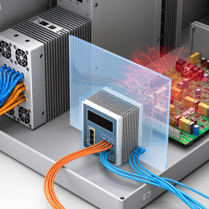
A digital signal isolator transfers digital information between two circuits without a direct electrical connection. A tiny isolation barrier separates its input and output sides. Signals cross that barrier through methods such as capacitive or magnetic coupling. The logic state remains recognizable, even though current cannot flow straight between the circuits. In practical terms, a microcontroller can send a switching signal to a motor-control circuit while their grounds remain electrically separate.
This separation can reduce the effect of ground differences and electrical noise. It may also help protect sensitive circuitry, but an isolator does not make a system automatically safe. Its isolation rating, working voltage, signal speed, and channel direction must suit the application. Check the datasheet, especially when circuits switch quickly or experience sharp voltage changes. The terminology can be confusing, and a missed rating is an easy mistake. Isolation also adds propagation delay, so timing-sensitive designs need careful testing.
Tips: Trace the signal path on your schematic. Confirm which side powers each channel, then check timing and voltage limits. Test the assembled circuit under realistic noise conditions. A clean bench result is useful, but it may not tell the whole story.
How Does a Digital Signal Isolator Work?
A digital signal isolator transfers information across an insulation barrier without a direct conductive path. On the input side, a circuit converts each logic change into a brief pulse or modulated signal. Tiny capacitors or a transformer carry that signal across the barrier; a receiver then rebuilds the original high and low states. The signal crosses. The hazardous current should not. In real hardware, small parasitic capacitances remain, so isolation does not mean zero coupling.
The timing matters. IEEE 802.3 specifies 100BASE-TX operation at 100 megabits per second; one bit interval is 10 nanoseconds. An isolator must preserve timing and logic levels at the chosen data rate. IEC 60747-17:2020 sets insulation and test requirements for magnetic and capacitive couplers, including dielectric withstand and partial-discharge testing. These tests assess different failure risks; a headline isolation voltage alone cannot describe the whole device. Engineers also check working voltage, creepage distance, and common-mode transient immunity. A fast voltage jump across the barrier can create a false output pulse. That sounds simple. It is not always. Board layout and nearby switching currents can affect performance, and specifications do not fully predict every installed system. Testing the actual circuit remains important.
What Problems Does Signal Isolation Prevent?
A long sensor cable can connect equipment powered from different outlets, leaving their ground potentials slightly unequal. The resulting loop current may appear as a drifting temperature reading, a noisy waveform, or a controller reset. A digital signal isolator breaks the direct conductive path while passing data across an isolation barrier. It can reduce ground-loop interference and limit the spread of certain electrical disturbances. It is not a cure-all.
The disturbance levels are real. IEC 61000-4-5 defines surge testing with a 1.2/50 μs voltage waveform and an 8/20 μs current waveform. IEC 61000-4-4 specifies fast transient bursts with 5/50 ns pulses. These standards provide useful immunity-test benchmarks, not a promise that every field installation is protected. Check the isolator’s working-voltage, surge, and common-mode transient ratings against the system. Isolation also cannot compensate for poor grounding or inadequate circuit protection. A missed detail matters. In practice, inspect the cable route, grounding points, and device ratings together; choosing an isolator by data rate alone is an easy mistake to make.
Where Are Digital Signal Isolators Used?
Why Use a Digital Signal Isolator?
Where Are Digital Signal Isolators Used?
Digital signal isolators are used wherever digital information must cross between circuits with different electrical conditions. In factory automation, they can carry control signals between a controller and a motor drive. A switching motor may create electrical noise or ground differences that interfere with nearby logic. Isolation helps keep that disturbance from traveling directly into sensitive circuitry. It is useful, not magic.
They also appear in power converters, solar inverters, battery systems, and building controls. A temperature sensor beside a high-voltage power stage, for example, may send readings across an isolation barrier to a processor. Test instruments use isolation to reduce unwanted current paths between measurement points. In medical equipment, isolation may be part of a carefully engineered safety design, but a digital isolator alone does not make equipment safe for patient contact.
Design details matter. Engineers check the required isolation rating, signal speed, channel direction, and layout clearances for the application. They also consider what happens during startup or a fault. A barrier can reduce risk, but it cannot fix poor grounding or careless wiring. Real installations are messier than diagrams. That is worth remembering.
Why Use a Digital Signal Isolator? Where Are Digital Signal Isolators Used?
Digital signal isolators transmit logic signals across a galvanic isolation barrier without a direct conductive connection. They are commonly used in industrial control, motor drives, medical equipment, renewable-energy systems, and data-acquisition interfaces. The waveform below is a conceptual example; its timing is illustrative, not a device specification.
What Factors Guide Isolator Selection?
Selecting a digital signal isolator begins with the signal itself. Check its data rate, pulse width, channel count, and direction. A fast bus may need low propagation delay and small channel-to-channel skew. For a slow status line, those specifications may matter less than power use or board space. Start with the actual interface, not the most impressive number on a datasheet.
Then examine electrical stress. Compare the isolator’s continuous working voltage with the system voltage, and check its transient withstand rating separately. They describe different conditions. Common-mode transient immunity also matters when noisy switching nodes sit near sensitive control signals. Check the required insulation standard for the equipment, too. A high isolation rating alone does not confirm that the full design meets its needs.
Look at temperature range, supply voltage, package, and electromagnetic compatibility. These details affect performance after the part leaves a tidy schematic and enters a crowded board. Allow room for proper spacing, and follow the manufacturer’s layout guidance. A useful habit is to test the isolator under realistic voltage and noise conditions before production. One detail is easy to miss: the isolator’s own power arrangement can limit otherwise suitable channels. Datasheets help, but real board constraints deserve a second look.